.
You can find many more electronic circuits for beginners by clicking the link!

H bridge circuit

An H bridge is a kind of circuit you use to control the direction (and sometimes speed) of an electric motor, using only a single polarity voltage (you need to reverse the way current flows in order to reverse the way the motor rolls).

How it works:

You have 4 transistors, wired as ON OFF switches. Two signal lines allow you to run the motor in one direction, when reversed, the motor runs in the other direction. It's very straightforward to use and build, but be careful to use only small motors, as the currents drawn from the bigger types can burn your components.

There are 3 modes of operation:
Both equal ( on or off ): motor doesn't run, as it's shorted or not connected
S1 on, S2 off: motor runs in reverse ( from negative [blue] to positive [red] )
S1 off, S2 on: motor runs normal.

Also note, unless you use power transistors, you need to connect diodes across the transistors in order to protect from overvoltages.

Simplified schematic:


Tone generator circuit

Simple, low component count tone generator. It can be adapted to create a morse code circuit, by adding a switch to the output.

How it works:

This circuit is based around the 555 timer circuit, used as an astable (free running) oscillator. The frequency (pitch) of the tone is set by the resistors and capacitors in the left side of the circuit. The first one is a potentiometer (variable resistor), this is our pitch control, which is basically all the external components you need. The capacitor to the far left is to reduce as much noise or undesired operation of the potentiometer, getting a smooth pitch change when adjusting.


You can find the timer's datasheet by following the link: 555 timer

Simple power supply

This circuit is very useful in beginners circuits, since most will work on 5v, which is the voltage of this easy little circuit.

How it works:

This circuit is just an implementation of the 7805 integrated voltage regulator. What this little component does is to lower a voltage and stabilize it by reducing noise and ripple, in order for circuits to have the constant voltage needed to work correctly


You can find the datasheet by following the link: 7805, take note of the typical applications notes, you can find some more uses for this versatile little regulator

Led Chaser

This Led chaser is built using some very common digital logic circuits. Easy to build, easy to work with, and looks amazing in the dark. This circuit will light each led in sequence, creating a moving light illusion.

How it works:

From left to right, the first IC is a binary counter, 74ls163, that is used to generate the address numbers we are going to use in the second part of the circuit, the demultiplexer 74ls138. This demux is the core of the circuit, as this IC pulls low the pin selected in the address inputs. Note that you need an external clock for the counter to work (count).

This is a very simple circuit to build, just take note of the control pins on each IC, since both have enable inputs for counting or output, but once set you don't need to worry about them. It can also be extended to 16 leds by using the Q3 output of the counter to control the enable inputs of a second demultiplexer, or just add a second one to generate a double pattern.


You can find the datasheets for both IC's by following the links: 74ls138 | | 74ls163

Inductor

An inductor is a loop of wire that stores energy in the form of a magnetic field. It has uses in oscillators, filters, voltage sources and converters.

Theory checklist:
  • Inductive Reactance
  • Back EMF
  • Q factor
Modes of operation:
  • LC filters and the tank circuit
  • Autotransformer
  • Transformer

Transistor

A transistor is a semiconductor active device that amplifies or switches and electrical signal. It is used in amplifiers, digital electronics and buffer circuits.

Theory checklist:
  • Gain
  • Bias point
  • Saturation and cutoff
Modes of operation
  • Common base, emitter and collector configurations
  • Logic gates

Diode

A diode is a semiconductor device that allow current to flow in only one direction. Depending on the type of diode, it has uses as voltage rectifier, indicator and regulator.

Theory checklist:
  • The P-N junction
  • Forward and reverse bias
Modes of operation:
  • Rectifier
  • Diode as reference voltage
  • The zener voltage regulator
  • The led diode indicator
  • The varicap variable capacitor
  • The photodiode light sensor

Capacitor

Storing charge - the capacitor

To understand how another component in electronic circuits works, imagine the following:

Imagine that we have two 'boxes' to put charged particles separated by a piece of plastic. We fill the top one with positive charges and the bottom one with negative charges, only the positive charges are allowed to move. We know that they will try to come together because of the forces generated by opposite charges, but since they cannot get out of the box, the are just stored there not doing any work.

Now imagine that we connect the two boxes with a pipe through where the charges can move. The positive charges will move to meet with the negatives and be in equilibrium. Now that they are moving, there's work and energy being expended that can be put to use.

The device that accomplishes this is called a capacitor. Basically they are two conductor plates separated by an insulator layer, in effect creating the two boxes mentioned above.

When we connect a voltage source to a capacitor, the capacitor is 'empty', with no charges, then charges from the source will start filling it up. As more and more charges reach the capacitor, they will start exerting a force on the charges trying to come in from the source, so it will start filling slower and slower.

Once the capacitor is filled, no more charges flow from the source to the capacitor. If the voltage source is removed, the charges the capacitor has remain there, waiting for something to allow them to meet with opposite charges to reach equilibrium.

If we connect a resistor across, the potential difference created by the separated charges in the capacitor allow it to function as a voltage source, so these charges start flowing through the resistor. As more charges flow, the capacitor starts emptying, causing less potential difference over time, until it can no longer provide charges and the current flow stops.

One way to picture the charging and discharging of a capacitor is to think of a balloon with two mouths, one connected to an air pump and the other left open simulating the resistor through which charges escape. The pump will inflate the balloon to a certain pressure that will be kept constant by the air that escapes the balloon through the other mouth.

If a sudden increase in pressure from the pump occurs, the balloon will inflate more but the air coming out will remain at about the same level, increasing until the air that comes in is the same air that comes out. If the increase in pressure is short, the balloon will inflate and deflate quickly, and the air coming out would remain almost the same throughout.

Same happens with capacitors, when a sudden spike in voltage occurs, the capacitor stores the charges and the voltage in it rises slowly, outputting about the same current throughout the process. This property gives capacitors most of its uses with direct current circuits.

Resistor

Resistors

Resistors are electronic and electric components that oppose the flow of current in a circuit. They are made from relatively poor conductors but that don't stop current from flowing altogether.

There are many kinds of resistor constructions, each suited for many purposes that overlap.

The simplest form is a cylinder of carbon material with two connection leads attached at both sides. The diameter and length of the cylinder, as well as the carbon composition of the filling determine the resistance. In general, a longer cylinder has more resistance than a shorter one, and a thicker one will have less resistance than a thin cylinder.

The apparent counter intuitive nature of a thick resistor having less resistance lies in how current flows in a circuit: it will always look for an easier path, and with a thick resistor with more overlapping paths, current has a higher chance of finding an easier path than in a limited and crowded thin resistor.

Another construction method is to coat a ceramic core with a resistor material and shape it in the form of a spiral by removing some of the material along the edge of the spiral. Since this method effectively increases or decreases the length of the resistor material, resistance can be carefully selected and determined.

High power resistances use that same method but instead of resistor material covering a core, resistive wire is used to allow for better heat handling.

Resistors have a standard color code that reflects the value of the resistance of the component. It consists of four color bands, the first two represent numbers and the third represents the number of zeros to add at the end of such number (more on the color code).

Series and parallel resistors

Series when only two components, in this case resistors, share only one of their connections; It could also be described as connecting one resistor after the other forming a chain.

From the construction characteristics of resistors, we can see that when we connect resistors in series, we are effectively creating a single, longer resistor, so what happens with the total resistance?

Simple, they are added together.

For example, we have a square tube we will fill with water. If we wanted to know the volume, we multiply base times height of the water in it to get the volume of water we put in. We measure separately the volume of a one by one cube of water and another of one by two, and get 1 and 2 respectively. We then fill tube with both, how much volume is the water in the tube?

We only put in 3 units of volume, and if we know that none leaked out of the tube, there can be no less than 3 units. So in effect the volumes add together.

Now the volume can be thought as the resistance, put two resistors into a single line and their resistances add up. No math involved, although there's a math proof of this derived from ohm's law.

Parallel is when two or more components share both of their connections together.

What happens with the resistance in parallel circuits? It happens something similar as having a thicker resistor, but not for the same reasons.

Imagine a circuit with one voltage source and two resistors in parallel, both resistors draw current from the source. From the point of view of the source, providing more current to the circuit is the same as providing current to a lower valued resistance, following I = V/R. To know exactly how much resistance the source 'sees' we have to do some math.

It = V/R1 + V/R2 : where It is the total current supplied by the source, R1 and R2 the respective resistances.
V/Rt = V/R1 + V/R2 : We replace It with V/Rt, since we want to know the total resistance the source 'sees'
1/Rt = 1/R1 + 1/R2 : Divide both sides by V

From this last formula we see that the inverse of the resistance is what's added thogether. The formula can be further worked to result in a simple, easy to remember formula.

1/Rt = (R1+R2)/(R1*R2)
Rt = (R1*R2)/(R1+R2)

Note that this only works for two resistors.

Voltage Follower Circuit

Two examples of the most common types of Voltage followers (buffers). You can find some theory behind them in our amplifier gain and buffer amplifier pages.

Transistor voltage follower:

This first circuit is a very simple one transistor voltage follower. Consist of two biasing resistors, and one other resistor at the emitter to acquire the output voltage from.

How it works:

The first to resistors connected to the transistor's base are forming a voltage divider, in order to set a biasing point for the transistor to work in our desired range. Then the transistor, our gain component for the circuit which in this case is only used as a gateway to isolate two circuit stages.

The resistor in the emitter is used to create a voltage from the current passing from the transistor; Without it we can't get any voltage as our output would be effectively shorted to ground (0 volts).

The capacitors that are displayed in the schematic are optional, but very useful to prevent a wrong operation of the circuit, specially in audio or high frequency uses. they stop any DC voltage to move or otherwise disrupt the bias point of the transistor, thus causing undesired operation. If you build this circuit only with dc remove the capacitors, as they will prevent the circuit from functioning under those conditions.


Transistor voltage follower

Op Amp Voltage Follower:

This circuit's operation is far more predictable and stable than the transistor version, and also requires less external components.

How it works:

Works as described above, no external elements to explain. This circuit uses feedback to maintain the voltage output the same as the input. Note that this schematic does not display power, ground and other connections for the op amp, these vary widely among manufacturers and op amps so refer to your op amp's datasheet for pinouts and power connections.


Opamp voltage follower

Buffer amplifier

A buffer amplifier, or simply a buffer, is an electronic amplifier that is designed to have an amplifier gain of 1. Buffers are used in Impedance matching, the benefit of which is to maximize energy transfer between circuits or systems.

There are two main kinds of buffer circuits, Voltage buffers and Current buffers. The purposes of each is to isolate the mentioned characteristic to avoid loading the input circuit or source from the output stage.

Another name by which buffer amplifiers are known as is a voltage follower. The name is given because of the characteristic of the amplifier to output a signal of the same amplitude as the input (given the unity gain [gain of 1 or 0dB] ).

Examples of Buffer amplifiers:

The examples are too many to mention in this page, the most common being the transistor voltage follower and op amp version of it. The exact characteristics, formulas and construction instructions can be found on the specific component's page.

Amplifier Gain

This is one the main characteristics to determine when designing or choosing an amplifier. This is a measure of the increase (or decrease in case of negative gain) the amplitude of the input signal.

Representation:

There are a few different ways to represent amplifier gain. One of the more common way among beginners and hobbyists, specially for DC or small signals, is to describe gain as the ratio of input vs output amplitude:

Gain = Vout/Vin, Where both input and output are either voltage or current (amperage).

Another way to represent amplifier gain is using a logarithmic decibel scale (dB). This representation is calculated using the ratio of input/output powers using the formula:

Gain = 10log(Pout/Pin)

Utility of gain:

There are countless applications and uses for amplifiers, since in the electronics world most signals we get from sensors or transmission lines is very small. There are also other times when not the amplitude of the signal is required but its power to transform into useful work, like when powering a motor, transmitting a radio signal and displaying an image on a screen.

How to calculate:

The specifics of how much gain can an amplifier have depend heavily on the components or circuits used, as well as the topology (configuration) of the amplifier. You can have a better understanding of the formulas used for each component and configuration by going to the specific page.

Amplifiers

Amplifiers increase either the amplitude (voltage) or power (Amperage/Current)
applied to its input.

Components of an amplifier:

Gain component: The main component of the amplifier, defines many of its characteristics like noise, bandwidth, gain, input and output impedance, and others.

Bias: Some types of components need a bias point in order to operate correctly. The bias point is a dc voltage applied to the input of the amplifier. There are many ways to set the bias point,
depending on the gain component used.

Accessories: These are many kinds of sub-circuits used to fine tune the operation of the amplifier, including preamplifiers, buffers, stabilizers, filters, limiters, etc..

Stages of Amplifiers:

Input: This stage consists of a signal from another subsystem outside the amplifier, or a sensor like a microphone, photodiode or any other component that delivers a small signal. Depending on
the intended purpose and input signal, this stage may contain a preamplifier, which is a signal (voltage) amplification before the main power (current) amplification stage, and a filter to
limit incoming frequencies.

Amplification: Main stage of any amplifier, most of the times it is a power amplification process, sometimes with signal amplification as well. This stage is where the gain component and many of the accessories like stabilizers and limiters are located.

Output: Last stage, sometimes consists of a buffer and/or filter to remove any noise generated in the main amplification stage. The buffer sometimes added to deliver more current (lower output impedance).


Block Diagram of a Amplifiers
(Click to enlarge)


Description of Amplifier accessories:

Coupling: This is usually done with a capacitor. The purpose of the coupling capacitor is to prevent any DC voltage from modifying the bias point of the amplifier, to prevent clipping (driving the signal to the max voltage, distorting it) from a high or low bias point.

Another coupling method is using transformers. This is done on lower frequency signals where the reactance (resistance-like behavior when a component is applied an AC voltage) of capacitors is so high to the point the signal is practically lost.

A third choice is using tuned transformers, by using a capacitor in parallel with the transformer. This creates a tuned circuit that has a very narrow bandwidth, useful in some special interest amplifiers.

Filters: This topic is so extensive it deserves its own article. Amplifiers have uses for filters to limit noise and reject unwanted signals from its input. Combining a filter and an amplifier creates an active filter (filter that has gain).

Most filters use RC networks to create the filter, although RL or RLC are also used in some designs.

Stabilizers: This is usually some kind of feedback used to prevent clipping or other circuitry to keep the frequency within a certain range (stop frequency drifting).

Limiters: Sometimes only voltages up to a certain point are needed or desired, here limiters come into use. They limit or sometimes clip a signal if it goes above a certain voltage, other kind of limiters use feedback to control the gain of the amplifier so as to keep the output signal within the specified voltage range.

Buffers: Also called voltage followers, this is just another name for another stage of amplification with a gain of 1. This is to provide more current and avoid overloading the main amplifier, as doing so can reduce either the gain or bandwidth.

If you need a specific implementation of an amplifier circuit, you may want to consider learning all the abstract theory first and then moving on to the components page, where all component-specific circuits and modes of operation are listed.

Types of circuits

From the smallest circuit to the largest electronics project, every circuit that performs a useful function has one or more of the same building blocks. I’m not talking about electronic components; I’m talking about sub-circuits that have a defined function.

These circuits are divided in digital and analog. In these pages you’ll learn how to design every type of circuit listed, with emphasis on a functionality level, instead of a component level, in order to be able to create any kind of amplifier as required by the project. Here’s the list of them:

Analog
  • Amplifiers
  • Filters
  • Power sources
  • Oscillators
  • Rectifiers
  • Timers
  • Modulators
  • Demodulators
Digital
  • Logic gates
  • Counters
  • Encoders
  • Decoders
  • Flip-Flops
  • Multiplexers
  • Demultiplexers
  • Analog to Digital Converter (ADC)
  • Digital to Analog Converter (DAC)
  • Microcontrollers
  • Microprocessors
All of these sub-circuits have a defined function within a complete project, and some of them are even a project on their own. These categories are somewhat broad; every one of them has many different designs and implementations depending on the particular characteristics of the project, for example amplifiers.

There are transistor and OpAmp amplifiers. In transistor amplifiers there are common source, common base, common collector, there are Darlington amplifiers. Transistor amplifiers are further divided by the kind of transistor used: BJT, N-channel JFET, P-channel JFET, MosFET, Nmos, Pmos, Cmos; Each with its own set of configurations.

On OpAmp there are negative feedback, positive feedback, voltage follower and others.
As you can see there are a million different combinations of amplifier topologies as they are called, way too many to be familiar with all of them.

Audio Amplifier

Here is a simple audio amplifier circuit that is easy to build and has few components. This circuit is built around the LM386 (click for datasheet) audio amplifier integrated circuit, useful when you need to power medium sized speakers from a music player that can only drive earphones.

How it works:

From left to right, the first part is the input stage, here is the connector to the audio source connected too the circuit using a capacitor. This capacitor passes only the audio, and blocks any direct current that may affect the function of the amplifier. Next to the capacitor is a variable transistor (potenciometer), this is used as a volume control.

Next is the LM386 itself, this amplifies the audio input using energy from the battery it is connected to. You'll notice there are two capacitors connected to it, one above and one below in the schematic. The top one is connected from pin 1 (positive side of capacitor) to pin 8 (negative side), this is to get the maximum amplification this IC can generate. The bottom one is also there to help get maximum amplification, this one goes connected from pin 7 (positive) to ground.

Last is the output stage, it is made with two capacitors, one resistor and the speaker. The resistor and capacitor that are connected before the speaker form a filter, that attenuates high frequency signals coming from the amplifier, most likely noise picked up or generated in the amplifying process. The capacitor connected to the speaker is there for the same reason we used a capacitor in the input stage, to prevent direct current from causing undesired operation of the speaker.

amplifier circuit using 386 electronic circuit
(click to enlarge)

Led Flasher Circuit

This circuit is built around one of the most popular timer integrated circuits, the 555 timer.

This circuit will flash the led on and of at regular intervals.

How it works:

From left to right, the two resistors and the capacitor set the time it takes to turn the led on or off, by changing the time it takes to charge the capacitor to trigger the timer. Next is the 555 timer, this is where all the work gets done to determine the time the led stays on and off. It contains a complicated circuit inside, but since it is packaged in the IC it can be used as a simple component.

The two capacitors that are right of the timer are just accessories so to speak, but are needed for the timer to work correctly. The last part is the resistor and the led, the resistor is there to limit the current on the led so that it won't burn.

555 led flasher circuit
(click to enlarge)

(click to enlarge)
(pin numbers on actual IC)

Simple FM Transmitter

This circuit uses a small microphone to capture the sound and some transistors to generate radio waves that can be picked up by a FM receiver like a car stereo.

How it works:

From left to right, the first part is the microphone and some resistors to get it working. Next we have a capacitor and the first transistor, this amplifies the sound from the microphone so that it can be loud enough to work with. The last part, there is a transistor, a coil and some capacitors. This part generates the radio waves and combines them with the sound from the mic to transmit it thru the antenna.

The coil is made with about 9 turns of wire, use a pencil to get the right diameter for the coil. The capacitor with the arrow is called a trimmer capacitor, it has a small screw to adjust the value, we'll use it to tune a certain frequency or station to transmit on.

simple fm radio transmitter(click to enlarge)

Logic Gates

Logic gates are the basic building blocks of digital electronics. These are circuits made out of transistors that perform a a logical operation (see Boolean algebra).

Digital electronics represent data (called bits) with only two states. Since in electronics we work with voltages, these two states are most times represented by a presence or lack of voltage. One (high state) in TTL logic familiy is represented by 5v, zero (low state) is represented by 0v (ground).

There are three basic gates: AND, OR, and NOT (Inverter).
Other common gates are NAND, NOR, XOR, XNOR (Equivalence). These gates are made with combinations of the basic logic gates. Its functions can be represented using a truth table, which lists every combination of inputs (A, B) and the resulting output (Z).

AND gate: two input gate, will output 1 when both inputs are 1. It is a one bit multiplication in Boolean algebra.

A B | Z
--------
0 0 | 0
0 1 | 0
1 0 | 0
1 1 | 1

OR gate: two input gate, will output 1 when one or both inputs are 1. It is a one bit addition.

A B | Z
--------
0 0 | 0
0 1 | 1
1 0 | 1
1 1 | 1


NOT gate or Inverter: one input gate, will output 1 when the input is 0 and viceversa.

A | Z
------
0 | 1
1 | 0


NAND gate: two input gate, same as AND gate but with a NOT at its output. Will output one as long as both its inputs are NOT 1. if none or one of the inputs is 0 it will output 1.

A B | Z
--------
0 0 | 1
0 1 | 1
1 0 | 1
1 1 | 0


NOR gate: two input gate, same as OR gate but with a NOT at its output. Will output one as long as none of its inputs are 1. if both inputs are 0 it will output 1.

A B | Z
--------
0 0 | 1
0 1 | 0
1 0 | 0
1 1 | 0

XOR gate: two input gate, will output 1 when one of its inputs is 1, but not both. This gate is actually a combination of gates, its boolean equation is A'B + AB'.

A B | Z
--------
0 0 | 0
0 1 | 1
1 0 | 1
1 1 | 0

XNOR gate or Equivalence: two input gate, will output 1 when both its inputs are the same, either 0 or 1. XOR gate with a NOT at its output, its boolean equation is A'B' + AB.

A B | Z
--------
0 0 | 1
0 1 | 0
1 0 | 0
1 1 | 1

Gate Diagrams:
Basic logic gates diagrams

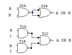
Building other gates with NAND and NOR:

NAND and NOR gates have a remarkable characteristic, with enough of either one of them and connected in a certain way you can actually recreate the behavior of any other gate. This ability has made them very popular for large scale manufacturing of logic gates, since it is cheaper to build only one kind of device instead of having separate machines to create different logic gates for a single circuit.

Here are the circuit diagrams to create other gates with NAND and NOR.

AND gate:
AND equivalent with NAND and NOR gates
OR gate:
OR gate with NAND and NOR diagram
NOT gate:
NOT gate with NAND and NOR diagram
NAND gate:
NAND gate with NAND and NOR diagram
NOR gate:
NOR gate with NAND and NOR diagram
Since all digital electronic circuits are made with transistors, you can make all the above gates using them. When creating logic gates with transistors, the best option is to make them using NAND, NOR and simple NOT gates. The benefit of this is that any other gate can be constructed with a slight variation in the number and configuration of the transistors, instead of having several different circuits for each gate.

Logic gate's transistor diagrams:

NAND gate:
NAND logic gate made with transistors
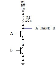
For this gate, the transistors are connected in series, so that the path from the output to ground is completed (thus giving 0 as output) only when both transistors are on (both inputs 1)

NOR gate:
NOR logic gate made with transistors
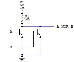
For the NOR gate, the transistors are connected in parallel, so that the circuit from the output to ground is closed when either transistor is on.

NOT gate:
NOT logic gate made with transistors
This gate is the simplest one to build with transistors, the NOT gate requires only one transistor. Here the transistor is configured so that when it is on (input 1), the circuit to ground is closed (output 0) and viceversa.

With these schematics and the above diagrams you can create a complete digital circuit using only transistors and resistors. Digital gates are very flexible, but up to a point. When creating a circuit that has more than three or four inputs, the circuit becomes too large to build using only logic gates, and that is where programmable devices come in handy, which we'll discuss in another article.

Privacy Policy

I do not collect any personally identifiable information such as names / email addresses.

I use Google Analytics to collect information about visitors, such as location, browser type, and other traffic stats. None of this information is personally identifiable and I use it only for improvement of the site and statistical analysis.

I use the Google Adsense program to display ads in this site, their own privacy policy is listed on their site.

Please note that I cannot control over other people's use of your private information on other sites, so if you leave this site you may want to check their own policies about the information they collect about you.

This site may use cookies, you can disable or delete them if you want.

Any questions please leave a comment and I'll answer it if I can.

Welcome To Electronic Circuits For Beginners!

All circuits included here are recommended to be assembled in printed circuit boards. Printed circuit boards, or PCB's increase the circuit reliability and mechanical stability.

Circuits quick links:

-

Simple FM Transmitter

-

Led Flasher Circuit

-

Quadrocopters for beginners

-

Voltage follower circuit

-

Beginners Audio Amplifier

-

Led chaser circuit

-

Tone generator circuit

-

H bridge circuit

-

Simple power supply

-

Beginner Electronics mini course index

-

All circuits include parts list and complete How-it-works for beginners and hobbyists to easily understand.