Any number of flip flops can be grouped together that share the same clock signal and work as a single unit. Common numbers of flip flops grouped together in a register are 4, 8, 16, and 32 (corresponding to 2^2, 2^3, 2^4 and 2^5).
A register functions as a more complete unit of memory within a circuit, grouping together data with a similar meaning in most cases, or just a more compact way of storing a bunch of bits. Most registers are made out of D flip flops due to the lower pin count needed for signals (JK would need much larger IC's because of the need for more control pins space).
There are four main kinds of registers, categorized by the way in which data is put in and taken out.
Parallel In, Parallel Out Registers
This kind is the simplest of registers. A parallel in/ parallel out is just a collection of flip flops that share a common clock signal but have independent data signals and outputs.
Their main application is storing data or state information (represented in binary digits) for use in later steps in sequential circuits.
Serial In, Parallel out Registers
Serial in/ parallel out registers get their input from a single data line. The output of the flip flop is used as one of the outputs, as well as connecting it to the data line of the next flip flop. What this accomplishes is that for every clock signal, the bits stored move one place and a new bit is captured at the first flip flop; the last flip flop is used just as another output, so its data is rewritten after every clock pulse.
This type of registers are used as buffers in digital data lines, where data is sent using only one wire but each bit is needed separately for further use.
Parallel in, Serial Out Register
Parallel in/ serial out registers have special control circuitry (sometimes a simple multiplexor suffices) that can select whether to use an external set of bits or the previous flip flop's output as input.
This is so that there's a possibility to get an external set of bits all at one (in parallel), and send them along one by one. Since each clock pulse the data moves to the next flip flop, the last can be used as the register's serial output, sending the data it stores one bit at a time.
In contrast to the receiving and "semimultiplexing" action of the serial in/ parallel out, the parallel in/ serial out combines number of data lines into a single one, most likely for transmitting over a digital line.
Serial in, Serial out Register
Kind of a special purpose register. This is always wired so that the first flip flop gets external data, and all internal flip flop's outputs are connected to the input of the next, the last one being used as output.
This register's main purpose is to delay the transmission of data in a digital data line.
Showing posts with label digital. Show all posts
Showing posts with label digital. Show all posts
The synchronous digital counter
Most situations need a counter that outputs only one value per transition, or in other terms, that all outputs change at the same time. In a ripple counter, when two or more bits need to change to reach the final output, intermediate outputs are generated, which can interfere with the correct function of other circuits that depend on the counter.
To overcome this limitation, the same clock signal applied to every flip flop to ensure that they all transition at the same time. The flip flop control signals now need some external logic to set them in the correct level for them to switch to the needed state.
The logic is simple: if all the previous flip flops are 1, then toggle the state (if 1, go to 0; if 0, go to 1). This is easily accomplished with an AND gate with N inputs where N is the number of previous flip flops, or its equivalent "cascaded" AND gates (one extra AND for every extra input, the output of a previous goes to an input of the next gate), which output will be connected to both J and K inputs in a JK flip flop, or adding an extra AND gate whose input is connected to the inverted output of the D flip flop.
The second flip flop is a special case, since there is only one previous flip flop to check, no logic is needed because it can be driven directly by the first flip flop's output.
To overcome this limitation, the same clock signal applied to every flip flop to ensure that they all transition at the same time. The flip flop control signals now need some external logic to set them in the correct level for them to switch to the needed state.
The logic is simple: if all the previous flip flops are 1, then toggle the state (if 1, go to 0; if 0, go to 1). This is easily accomplished with an AND gate with N inputs where N is the number of previous flip flops, or its equivalent "cascaded" AND gates (one extra AND for every extra input, the output of a previous goes to an input of the next gate), which output will be connected to both J and K inputs in a JK flip flop, or adding an extra AND gate whose input is connected to the inverted output of the D flip flop.
The second flip flop is a special case, since there is only one previous flip flop to check, no logic is needed because it can be driven directly by the first flip flop's output.

Applications of Sequential Logic: Digital Counters
Counters are one of the many applications of sequential logic that has a widespread use from simple digital alarm clocks to computer memory pointers. A counter is a collection of flip flops, each representing a digit in a binary number representation (which means each bit, depending on position, means a different number).
One of easier ways to build a circuit is to make a flip flop that controls the activation or switching of the second, and so on. This type of counter is called a ripple counter, since the switching signal propagates from one flip flop to the next as in a wave.
The Ripple Counter
For a simple ripple counter, JK flip flops with both inputs tied to 1 are the best option, since it will toggle state on the clock edge. For simplicity, the falling edge is used and assuming all flip flops start in reset state.
The first FF (Flip Flop) in the sequence gets the its input directly from the variable that needs to be counted. When it transitions from low to high to low again (this last transition generating a falling edge), in other words, when the input pulses, the FF changes to Set.
Since the First FF's output has not made a falling edge transition, the second FF remains Reset.
When another pulse appears at the input, the first FF changes to Reset again, creating a falling edge at its output, which triggers the second FF to transition to the Set state.
Another pulse, the first FF changes to Set; No falling edge at its output, the second FF keeps its state. Yet another pulse (Now four if you have been keeping the count), the first FF goes back to Reset, producing a falling edge; the second FF also goes back to Reset, producing a falling edge at its output that will trigger a third FF and making it Set.
If we assign the value of 1 to the first flip flop, 2 to the second and 4 to the third, we have a 3 bit binary number represented in there. Remember that with binary numbers, we add the values where the binary bit is set to 1.
As you can see, when all the transitions have occurred, the counter ends up with the count of input pulses it has received, representing them in a binary number.
The main drawback of this ripple counter is the fact that as the transition propagates from the first flip flop to the next, all the way to the last one, intermediate numbers are being set at the output, which introduces error and some confusion if a pure counter is needed.
This problem becomes most apparent when all the bits in the counter are set to 1 and another input pulse is applied: The output will be subtracted each time. In a 4 bit ripple counter, the max number that can be represented is 15 (1111), as the transition propagates, intermediate numbers 14 (1110). 12 (1100), 8 (1000) will appear before finally settling into 0 (0000).
One of easier ways to build a circuit is to make a flip flop that controls the activation or switching of the second, and so on. This type of counter is called a ripple counter, since the switching signal propagates from one flip flop to the next as in a wave.
The Ripple Counter
For a simple ripple counter, JK flip flops with both inputs tied to 1 are the best option, since it will toggle state on the clock edge. For simplicity, the falling edge is used and assuming all flip flops start in reset state.
The first FF (Flip Flop) in the sequence gets the its input directly from the variable that needs to be counted. When it transitions from low to high to low again (this last transition generating a falling edge), in other words, when the input pulses, the FF changes to Set.
Since the First FF's output has not made a falling edge transition, the second FF remains Reset.
When another pulse appears at the input, the first FF changes to Reset again, creating a falling edge at its output, which triggers the second FF to transition to the Set state.
Another pulse, the first FF changes to Set; No falling edge at its output, the second FF keeps its state. Yet another pulse (Now four if you have been keeping the count), the first FF goes back to Reset, producing a falling edge; the second FF also goes back to Reset, producing a falling edge at its output that will trigger a third FF and making it Set.
If we assign the value of 1 to the first flip flop, 2 to the second and 4 to the third, we have a 3 bit binary number represented in there. Remember that with binary numbers, we add the values where the binary bit is set to 1.
As you can see, when all the transitions have occurred, the counter ends up with the count of input pulses it has received, representing them in a binary number.
The main drawback of this ripple counter is the fact that as the transition propagates from the first flip flop to the next, all the way to the last one, intermediate numbers are being set at the output, which introduces error and some confusion if a pure counter is needed.
This problem becomes most apparent when all the bits in the counter are set to 1 and another input pulse is applied: The output will be subtracted each time. In a 4 bit ripple counter, the max number that can be represented is 15 (1111), as the transition propagates, intermediate numbers 14 (1110). 12 (1100), 8 (1000) will appear before finally settling into 0 (0000).
The JK Flip-Flop: An Improved SR Latch
The D flip-flop has some advantages over the standard latch, but there are some applications where the flexibility of extra control signals is just too much of an advantage to pass.
The transformation from simple RS latch to JK flip flop is done by connecting them in a Master-Slave configuration like the D flip flop, the non inverted output of the first latch to the Set input of the second, and the inverted output to the Reset.
At this point we still have just an edge triggered SR flip flop, meaning the forbidden condition is still there. To prevent it from happening, we extend the enabling logic of the first latch from a two input AND gate to a three input gate (or alternatively, connecting the output of the first and gate to one of the inputs at the second, and use the second output as the final output of the now three input gate).
The extra input is taken from the inverted output of the flip flop as a whole (the output of the second latch) for Set and the non inverted output for Reset. What this does is that when the flip flop is Set (output = 1) the Set connection gets disabled (negated output = 0) by since not all the inputs of the AND gate will be 1; This is done because if the Flip flop is already set, there's no point in "setting" it again, so that input can be disabled safely.
When the flip flop is Reset, the output will be 0 and disable the Reset input, since it cannot be "More Reset" than it already is, so it can be safely disabled.
What happens when both are 1 at the same time? Since the only time the output will change states is at one of the clock edges, and since at any point one of the inputs will be disabled, the output will depend only on the input that is active.
If the flip flop is Reset and both inputs are 1, only the Set input will be enabled. At the clock edge, the flip flop will be set.
If the flip flop is Set and both inputs are 1, only the Reset input will be enabled. At the clock edge, the flip flop will be Reset.
As you can see, The JK flip flop will toggle states when both inputs are 1, eliminating the forbidden state and its disadvantages while still maintaining the flexibility of multiple control signals.
This Flip Flop is called JK just to distinguish it from the RS latch and its forbidden combination; they work very similar, but the hazard free of the JK flip flop made it deserve a special name for itself.
The transformation from simple RS latch to JK flip flop is done by connecting them in a Master-Slave configuration like the D flip flop, the non inverted output of the first latch to the Set input of the second, and the inverted output to the Reset.
At this point we still have just an edge triggered SR flip flop, meaning the forbidden condition is still there. To prevent it from happening, we extend the enabling logic of the first latch from a two input AND gate to a three input gate (or alternatively, connecting the output of the first and gate to one of the inputs at the second, and use the second output as the final output of the now three input gate).
The extra input is taken from the inverted output of the flip flop as a whole (the output of the second latch) for Set and the non inverted output for Reset. What this does is that when the flip flop is Set (output = 1) the Set connection gets disabled (negated output = 0) by since not all the inputs of the AND gate will be 1; This is done because if the Flip flop is already set, there's no point in "setting" it again, so that input can be disabled safely.
When the flip flop is Reset, the output will be 0 and disable the Reset input, since it cannot be "More Reset" than it already is, so it can be safely disabled.
What happens when both are 1 at the same time? Since the only time the output will change states is at one of the clock edges, and since at any point one of the inputs will be disabled, the output will depend only on the input that is active.
If the flip flop is Reset and both inputs are 1, only the Set input will be enabled. At the clock edge, the flip flop will be set.
If the flip flop is Set and both inputs are 1, only the Reset input will be enabled. At the clock edge, the flip flop will be Reset.
As you can see, The JK flip flop will toggle states when both inputs are 1, eliminating the forbidden state and its disadvantages while still maintaining the flexibility of multiple control signals.
This Flip Flop is called JK just to distinguish it from the RS latch and its forbidden combination; they work very similar, but the hazard free of the JK flip flop made it deserve a special name for itself.
Master-Slave Latch or Flip-Flop
There are several drawbacks with using the level gating approach, one of the most serious is the fact that during the time the enable signal is on, the control signals pass easily through the now transparent latch, causing every change in control signals to be passed along the output of the latch. This is of special concern when working with the bouncy contacts of a mechanical switch.
A good way to overcome this is by connecting two of these transparent latches in what is called a master slave configuration in which one latch is active during the high level of the enable signal and a second, which gets its input from the first, gets activated with the low level of the enable signal.
The latches themselves are not changed in any way, only the enable signal will be connected in a special way: the first gets the signal directly and the second gets an inverted version of it.
When the enable signal is low, the first latch is disabled by the control logic, so it holds its state (no change at the output). At the same time, the second latch is enabled by the inverted signal (~0 = 1) and so its output is the same as its data input, which is connected to the first latch. Since the first latch is not changing at this point, the output of the second latch will not change either.
The moment the enable signal goes high, the first latch is enabled and its input will be the same as its data signal due to the input logic used to overcome the forbidden combination. The second latch is at the same time disabled by the inverted enable signal (~1 = 0), so even when its data input changes due to the first latch changing its output, the final output of this configuration will not change.
As the enable signal falls back to a low level (goes to 0), the first latch gets disabled and holds the last bit of data it got, while the second now gets enabled and starts transferring its data input, which is connected to the output of the first latch, to its output. It is at this point where any data applied through the cycle gets its transfer to the final output of the circuit.
A master-slave latch, commonly known as flip-flop, is an edge triggered device, meaning that it will only perform its full function when the signal changes instead of using a signal level. In this example the D flip-flop is falling edge triggered, since the output only changes when the enable (or more commonly known as clock in edge triggered circuits) goes from high (1) to low (0).
A good way to overcome this is by connecting two of these transparent latches in what is called a master slave configuration in which one latch is active during the high level of the enable signal and a second, which gets its input from the first, gets activated with the low level of the enable signal.
The latches themselves are not changed in any way, only the enable signal will be connected in a special way: the first gets the signal directly and the second gets an inverted version of it.
When the enable signal is low, the first latch is disabled by the control logic, so it holds its state (no change at the output). At the same time, the second latch is enabled by the inverted signal (~0 = 1) and so its output is the same as its data input, which is connected to the first latch. Since the first latch is not changing at this point, the output of the second latch will not change either.
The moment the enable signal goes high, the first latch is enabled and its input will be the same as its data signal due to the input logic used to overcome the forbidden combination. The second latch is at the same time disabled by the inverted enable signal (~1 = 0), so even when its data input changes due to the first latch changing its output, the final output of this configuration will not change.
As the enable signal falls back to a low level (goes to 0), the first latch gets disabled and holds the last bit of data it got, while the second now gets enabled and starts transferring its data input, which is connected to the output of the first latch, to its output. It is at this point where any data applied through the cycle gets its transfer to the final output of the circuit.
A master-slave latch, commonly known as flip-flop, is an edge triggered device, meaning that it will only perform its full function when the signal changes instead of using a signal level. In this example the D flip-flop is falling edge triggered, since the output only changes when the enable (or more commonly known as clock in edge triggered circuits) goes from high (1) to low (0).
The D Latch
So far we've been working with the same RS latch and all its limitations, such as the forbidden combination of inputs. By providing additional input logic and merging the control signals we have a more robust latch that is less prone to the unstable conditions of the simple RS latch.
For this new latch, the set and reset control signals are merged into one, the data signal. To control the flip flop with only one signal, we have to make sure that the latch is set when the data signal goes high (set to 1) and reset when it goes low (set to 0).
With only one signal this task is easily accomplished with an inverter gate. The non inverted signal will go to the set input and the inverted signal goes to the reset input. The enable circuitry goes after this new input logic to make sure that when the latch is not enabled it will maintain its current state, which would not be possible without this interface logic (one signal would always be high due to the inverter).
This simple arrangement of input logic combined with a two gate latch make it a very popular choice for high density Integrated Circuits (IC's). Sometimes the IC's whole memory and sequential logic is implemented using only latches very similar to these.
For this new latch, the set and reset control signals are merged into one, the data signal. To control the flip flop with only one signal, we have to make sure that the latch is set when the data signal goes high (set to 1) and reset when it goes low (set to 0).
With only one signal this task is easily accomplished with an inverter gate. The non inverted signal will go to the set input and the inverted signal goes to the reset input. The enable circuitry goes after this new input logic to make sure that when the latch is not enabled it will maintain its current state, which would not be possible without this interface logic (one signal would always be high due to the inverter).
This simple arrangement of input logic combined with a two gate latch make it a very popular choice for high density Integrated Circuits (IC's). Sometimes the IC's whole memory and sequential logic is implemented using only latches very similar to these.
The RS Latch
This circuit is called an SR latch because of its Set and Reset function and control signals.
A basic latch can be built with two NOR gates, with the output of one to one of the inputs of the other. The free input on both gates are used as control signals, one to SET the output to 1, and the other to RESET the output to 0. When no control signal is applied, the latch keeps its previous state via the conditions set at the output being fed back as inputs, which result in a condition that keeps the output the same.
The way in which the gates are wired make the output of one gate being the non inverted output of the latch, and the other being the inverted output.
There's one combination that will break that relation: when both Set and Reset are 1, both outputs will be at a 0 level. This in itself is not a cause for major concern, but when we make both control signals go from high to low at the same time, a race condition occurs.
This is called race condition because the output depends on which of the control signals stay high longer will determine the latch's output. If the set signal goes to 0 first, then the latch will have a 0 output (Reset), if the reset signal goes to 0 first, then the latch will have a 1 output (set).
The combination that produces this behavior is called a restricted or forbidden combination, because there's no way to actually know which signal will end up designating the latches output, which is not very good in a logic design where everything is supposed to be in one state or the other with full certainty.
This kind of latch is called a transparent latch because there are no synchronization or enabling signals, which means that the output will change as soon as the signals make it change; the latch doesn't restrict the flow of data through it.
Controlling the latch: Level Gated Latch
One way to have better control over the functioning of the latch, a layer of AND gates are connected between the control signals and the actual latch's gates inputs. One of the AND inputs is shared and is connected to a new control signal: the enable signal.
This new signal controls the availability of the set and reset inputs to the actual latch. When the enable signal is 0, no matter what the set and reset signals are, the latch will never receive them, only 0 will appear since it is connected at the AND gate's outputs, so it will only hold its previous state.
When the enable signal is at 1, the output of the AND gates will depend on the set and reset signals, essentially letting them pass through to the latch. As you can see, this new layer of gates and a new signal allow us to control whether we want the the latch to function (enable it) or to just keep its previous state (when enable = false [0])
This kind of enable mechanism is called level gating, since the control signals will only reach the latch when the gates it needs to pass are enabled by the level of the enable signal.
A basic latch can be built with two NOR gates, with the output of one to one of the inputs of the other. The free input on both gates are used as control signals, one to SET the output to 1, and the other to RESET the output to 0. When no control signal is applied, the latch keeps its previous state via the conditions set at the output being fed back as inputs, which result in a condition that keeps the output the same.
The way in which the gates are wired make the output of one gate being the non inverted output of the latch, and the other being the inverted output.
There's one combination that will break that relation: when both Set and Reset are 1, both outputs will be at a 0 level. This in itself is not a cause for major concern, but when we make both control signals go from high to low at the same time, a race condition occurs.
This is called race condition because the output depends on which of the control signals stay high longer will determine the latch's output. If the set signal goes to 0 first, then the latch will have a 0 output (Reset), if the reset signal goes to 0 first, then the latch will have a 1 output (set).
The combination that produces this behavior is called a restricted or forbidden combination, because there's no way to actually know which signal will end up designating the latches output, which is not very good in a logic design where everything is supposed to be in one state or the other with full certainty.
This kind of latch is called a transparent latch because there are no synchronization or enabling signals, which means that the output will change as soon as the signals make it change; the latch doesn't restrict the flow of data through it.
Controlling the latch: Level Gated Latch
One way to have better control over the functioning of the latch, a layer of AND gates are connected between the control signals and the actual latch's gates inputs. One of the AND inputs is shared and is connected to a new control signal: the enable signal.
This new signal controls the availability of the set and reset inputs to the actual latch. When the enable signal is 0, no matter what the set and reset signals are, the latch will never receive them, only 0 will appear since it is connected at the AND gate's outputs, so it will only hold its previous state.
When the enable signal is at 1, the output of the AND gates will depend on the set and reset signals, essentially letting them pass through to the latch. As you can see, this new layer of gates and a new signal allow us to control whether we want the the latch to function (enable it) or to just keep its previous state (when enable = false [0])
This kind of enable mechanism is called level gating, since the control signals will only reach the latch when the gates it needs to pass are enabled by the level of the enable signal.
Sequential Logic: Circuits with memory
By using a circuit output as an input to itself so that the next output depends not only on the input signals that are applied at the moment but also on its current state (by feeding back the signal, which was in turn generated by a combination of previous inputs and outputs), we can create circuit that work in steps (sequentially).
To accomplish this we first need a subcircuit that will hold an output even if the inputs change. The most basic circuit that accomplishes this is called a latch.
To accomplish this we first need a subcircuit that will hold an output even if the inputs change. The most basic circuit that accomplishes this is called a latch.
Quick Logic Synthesis
Multiplexors are a simple combinational circuit whose function is to select one input line to pass to its only output, by selecting it using address/select lines, the number represented using the binary number system is the input that is being selected.
The input lines available often are a power of two (2, 4, 8, 16), and the number of select lines are the power to which 2 must be elevated to obtain the number of input lines (2^n = L, where n is the number of select lines and L is the number of input lines)
One way to look at the functioning of a multiplexer is that the select lines represent a row in the circuit's truth table, and the value connected to the corresponding input line is the output of that row, which will be passed to the final output of the multiplexer if that line is selected.
As you can see, this circuit can be used to implement an arbitrary truth table of n input variables (remember in the previous equation we used n to represent the number of select lines).
An advantage of this method over discrete gates in implementing a truth table is the fact that only one integrated circuit is used in practice, gates ussually needing more IC's because of lower integration (uses less gates per IC).
Boolean equations can also be implemented by first generating the truth table for it by evaluating the output variable for every possible input variable's value combination.
One disadvantage in using this method over discrete logic gates is the fact that since the multiplexer is not optimized for any particular configuration, so it tends to be slower in practice but such speed penalty affects only high speed and high gate count circuits.
Extending Quick Synthesis: ROM Logic Synthesis
The idea of using a somewhat generic circuit to implement any truth table without modifying the underlying circuit by using a multiplexor can be extended to the use of ROM modules in order to extend the number of input variables available (by having more address/select lines) and the number of outputs per combination (by having more output lines)
A ROM module is a type of memory circuit that is either built with its contents (Hardwired or Masked) or programmed (Programmable ROM). Each address selects a cell of memory (as opposed to a single line in the multiplexor) that contains the information to be passed to the output in groups of size that is a power of two (8 [2^3] and 16 [2^4] being the most common).
This allows us to implement simultaneous truth tables by programming each output line of each address as the output of one of those truth tables. It's basically like having many multiplexors connected to the same select lines, each implementing a different (or even the same) truth table.
The input lines available often are a power of two (2, 4, 8, 16), and the number of select lines are the power to which 2 must be elevated to obtain the number of input lines (2^n = L, where n is the number of select lines and L is the number of input lines)
One way to look at the functioning of a multiplexer is that the select lines represent a row in the circuit's truth table, and the value connected to the corresponding input line is the output of that row, which will be passed to the final output of the multiplexer if that line is selected.
As you can see, this circuit can be used to implement an arbitrary truth table of n input variables (remember in the previous equation we used n to represent the number of select lines).
An advantage of this method over discrete gates in implementing a truth table is the fact that only one integrated circuit is used in practice, gates ussually needing more IC's because of lower integration (uses less gates per IC).
Boolean equations can also be implemented by first generating the truth table for it by evaluating the output variable for every possible input variable's value combination.
One disadvantage in using this method over discrete logic gates is the fact that since the multiplexer is not optimized for any particular configuration, so it tends to be slower in practice but such speed penalty affects only high speed and high gate count circuits.
Extending Quick Synthesis: ROM Logic Synthesis
The idea of using a somewhat generic circuit to implement any truth table without modifying the underlying circuit by using a multiplexor can be extended to the use of ROM modules in order to extend the number of input variables available (by having more address/select lines) and the number of outputs per combination (by having more output lines)
A ROM module is a type of memory circuit that is either built with its contents (Hardwired or Masked) or programmed (Programmable ROM). Each address selects a cell of memory (as opposed to a single line in the multiplexor) that contains the information to be passed to the output in groups of size that is a power of two (8 [2^3] and 16 [2^4] being the most common).
This allows us to implement simultaneous truth tables by programming each output line of each address as the output of one of those truth tables. It's basically like having many multiplexors connected to the same select lines, each implementing a different (or even the same) truth table.
Minterms and Maxterms
Truth tables help determine the input combination that will yield a certain output value; This is useful when we want to translate a given truth table into a boolean equation that can be much easily manipulated and simplified before actually building a circuit, hopefully making the wiring eaasier and cheaper by using less components.
There are two complementary terms that we use to accomplish this: Minterms and Maxterms.
A minterm represents each row of the truth table that has an output of 1. To translate a truth table row into the corresponding minterm we AND (or multiply) each of the terms at the input, inverting (applying a NOT operator) to each variable whose state for that particular row happens to be zero.
For example, the three input truth table:
A B C Z
0 0 0 0
0 0 1 0
0 1 0 1 <---
0 1 1 0
1 0 0 1 <---
1 0 1 0
1 1 0 0
1 1 1 1 <---
The rows marked with an arrow represent the minterms of the table. The equation for this table would be
Z = (~A * B * ~C) + (A * ~B * ~C) + (A * B * C)
Note that all three minters go together in the same equation, since any of them can trigger an output 1 (if the first is true [1] OR [+] the second OR the third, the output is also true [1]).
Minterms are also called the sum of products representation because of the way they end up arranged in the equation.
Maxterms are the complementary operation of minterms. Maxterms are obtained from the rows that have a zero in them as output. Using the above example, all the rows not marked with an arrow are the table's maxterms.
To translate from the table to a boolean equation we OR (sum) each of the terms acting as input, applying a NOT operation to any input that happens to be a 1 for that particular row. Notice how the operation (AND for minterms, OR for maxterms) and the criteria for negation (when the input variable is 1 for minterms and when it is 0 for maxterms) are opposite of each other.
The equation in Maxterms for the example would be
Z = (A + B +C)*(A + B + ~C)*(A + ~B + ~C)*(~A + B + C)*(~A + ~B + C)
For this particular table, you can see that the equation in maxterms has more of them, this is because there are more 0's as output than 1's, and since each row having them is one term in the equation, the more there are the more terms the resulting equation will have.
The maxterm representation is also called a product of sums, because of the way they are arranged.
They are arranged in such a way because if any of them is 0, then the output should be 0 as well, even if the other terms are 1. This is because if one of the terms is 0, then it means that the combination of inputs matches one of the rows of the table that results in a 0 output, and no matter what the other terms are (any number multiplied by 0 is 0), the output should be 0 in order for the equation to work the same as what's specified in the table.
There are two complementary terms that we use to accomplish this: Minterms and Maxterms.
A minterm represents each row of the truth table that has an output of 1. To translate a truth table row into the corresponding minterm we AND (or multiply) each of the terms at the input, inverting (applying a NOT operator) to each variable whose state for that particular row happens to be zero.
For example, the three input truth table:
A B C Z
0 0 0 0
0 0 1 0
0 1 0 1 <---
0 1 1 0
1 0 0 1 <---
1 0 1 0
1 1 0 0
1 1 1 1 <---
The rows marked with an arrow represent the minterms of the table. The equation for this table would be
Z = (~A * B * ~C) + (A * ~B * ~C) + (A * B * C)
Note that all three minters go together in the same equation, since any of them can trigger an output 1 (if the first is true [1] OR [+] the second OR the third, the output is also true [1]).
Minterms are also called the sum of products representation because of the way they end up arranged in the equation.
Maxterms are the complementary operation of minterms. Maxterms are obtained from the rows that have a zero in them as output. Using the above example, all the rows not marked with an arrow are the table's maxterms.
To translate from the table to a boolean equation we OR (sum) each of the terms acting as input, applying a NOT operation to any input that happens to be a 1 for that particular row. Notice how the operation (AND for minterms, OR for maxterms) and the criteria for negation (when the input variable is 1 for minterms and when it is 0 for maxterms) are opposite of each other.
The equation in Maxterms for the example would be
Z = (A + B +C)*(A + B + ~C)*(A + ~B + ~C)*(~A + B + C)*(~A + ~B + C)
For this particular table, you can see that the equation in maxterms has more of them, this is because there are more 0's as output than 1's, and since each row having them is one term in the equation, the more there are the more terms the resulting equation will have.
The maxterm representation is also called a product of sums, because of the way they are arranged.
They are arranged in such a way because if any of them is 0, then the output should be 0 as well, even if the other terms are 1. This is because if one of the terms is 0, then it means that the combination of inputs matches one of the rows of the table that results in a 0 output, and no matter what the other terms are (any number multiplied by 0 is 0), the output should be 0 in order for the equation to work the same as what's specified in the table.
Logic Equations
Aside from representing the functioning of a logic gate with a truth table and a grammatical (with words) definition, the use of logic equations can be used not only to represent logic gates and circuits, but also with the usage of some theorems and equivalences, to reduce the number of terms involved, simplifying the equation.
In logic equation every boolean variable involved is assigned a letter or symbol, very similar to the algebraic representation of unknown numerical values using letters; In fact, this approach to logic is called boolean algebra due to their similarity (remember that it is called boolean variables and algebra because of the person who did extensive work on the subject, George Bool).
Each input variable is usually assigned one of the first letters of the alphabet (A, B, C, and so on), and the output variables are assigned the last letters (W, Y, Z, and so on; note that X was specifically left out, this is because it is used as a "Don't Care" condition in logic simplification). This assignment of letters is arbitrary, any other letter or symbol can be used instead, but it is a common way to assign them and most people working in the area follow this pattern.
The logic operations are either written in uppercase (OR, AND, NOT) or represented by their logical symbol (V for OR, ^ for AND, ~ or the variable name overlined for NOT). Parenthesis are used to order the operations and force precedent evaluation before using in other operations, similar as in algebra where the operations in deeper levels of parenthesis are evaluated first.
For example, to represent the AND operation, using A and B as input variables and Z as output, you can write
Z = A AND B
or alternatively
Z = A ^ B
For a more complex circuit where the order is not always clear (similar to algebra, the evaluation is always left to right since there are no operations of higher priority like division or multiplication are in mathematical algebra), the use of parenthesis is encouraged, for example:
Z = A AND B OR B AND C
could mean very different things depending on how it is interpreted, so the equivalent form
Z = (A AND B) OR (B AND C)
being much more explicit in what gets evaluated first is preferred.
Another way to represent the operations in a logical equation is to simply use the mathematical operators that closely resemble their operations (+ for OR, * for AND); the NOT gate is an exception to this, as well as most compound gate. The only compound gates that have a symbol associated to them are the XOR gate (a + sign enclosed in a circle) and the XNOR gate (since it represents a logical equivalence, the = sign or the three line equivalence sign is used).
In logic equation every boolean variable involved is assigned a letter or symbol, very similar to the algebraic representation of unknown numerical values using letters; In fact, this approach to logic is called boolean algebra due to their similarity (remember that it is called boolean variables and algebra because of the person who did extensive work on the subject, George Bool).
Each input variable is usually assigned one of the first letters of the alphabet (A, B, C, and so on), and the output variables are assigned the last letters (W, Y, Z, and so on; note that X was specifically left out, this is because it is used as a "Don't Care" condition in logic simplification). This assignment of letters is arbitrary, any other letter or symbol can be used instead, but it is a common way to assign them and most people working in the area follow this pattern.
The logic operations are either written in uppercase (OR, AND, NOT) or represented by their logical symbol (V for OR, ^ for AND, ~ or the variable name overlined for NOT). Parenthesis are used to order the operations and force precedent evaluation before using in other operations, similar as in algebra where the operations in deeper levels of parenthesis are evaluated first.
For example, to represent the AND operation, using A and B as input variables and Z as output, you can write
Z = A AND B
or alternatively
Z = A ^ B
For a more complex circuit where the order is not always clear (similar to algebra, the evaluation is always left to right since there are no operations of higher priority like division or multiplication are in mathematical algebra), the use of parenthesis is encouraged, for example:
Z = A AND B OR B AND C
could mean very different things depending on how it is interpreted, so the equivalent form
Z = (A AND B) OR (B AND C)
being much more explicit in what gets evaluated first is preferred.
Another way to represent the operations in a logical equation is to simply use the mathematical operators that closely resemble their operations (+ for OR, * for AND); the NOT gate is an exception to this, as well as most compound gate. The only compound gates that have a symbol associated to them are the XOR gate (a + sign enclosed in a circle) and the XNOR gate (since it represents a logical equivalence, the = sign or the three line equivalence sign is used).
Truth Tables
In order to graphically and orderly present each possible output from a logic gate or any digital circuit, a truth table is used. These tables present every possible combination of input states and its corresponding output.
The first columns represent each of the input variables, and the last one (or few if there's more than one) represent the output of the circuit. For low number of variables (lower than 4 or 5) the number of possible combinations is small enough to be able to represent in a truth table, and all possible input combinations and their corresponding output can be quickly visualized.
The first columns represent each of the input variables, and the last one (or few if there's more than one) represent the output of the circuit. For low number of variables (lower than 4 or 5) the number of possible combinations is small enough to be able to represent in a truth table, and all possible input combinations and their corresponding output can be quickly visualized.
Binary Representations
A logic system is one that anything it does can be translated to a true or false, present or absent, high or low, in other words, two opposite and contrasting states where the system can only be at one of them at any one time. Digital electronics use only two voltage levels to work with, one to represent a true, 1 or high (usually 3v or 5v) and another to represent false, 0 or low (a connection to ground, which is at 0v), which make the basis of any logic system.
But what does a true represent in a logic circuit? anything you can think of, it depends on what you are using it to model. One of the most used introductory digital systems is that of a car key alarm, where if the door is open while the key is still in the ignition, a buzzer alarm will sound alerting you not to let the key inside the car when you close it.
To construct a digital circuit for this alarm, you use one input to represent whether the door is open (will be true when it is open, false when closed) and another to represent whether the key is in the ignition (will be true when in the ignition, false when not). For this circuit we want the buzzer to sound when both conditions are true: the door is open and the key is in the ignition.
A digital system is not concerned if the key is only half in, at the on or off position or if the car is only half open or it didn't close correctly; all of these situations are either forced to one state of the other, or switching between both at a very high rate, but it must have one of only two values.
As you can see, we have modeled a fairly complex situation (an alarm controlled by a door and a key) to only two inputs that take only two values. This is what makes digital circuits very useful, they are dependable (a half closed door is an open door, just as a slightly open door).
But what does a true represent in a logic circuit? anything you can think of, it depends on what you are using it to model. One of the most used introductory digital systems is that of a car key alarm, where if the door is open while the key is still in the ignition, a buzzer alarm will sound alerting you not to let the key inside the car when you close it.
To construct a digital circuit for this alarm, you use one input to represent whether the door is open (will be true when it is open, false when closed) and another to represent whether the key is in the ignition (will be true when in the ignition, false when not). For this circuit we want the buzzer to sound when both conditions are true: the door is open and the key is in the ignition.
A digital system is not concerned if the key is only half in, at the on or off position or if the car is only half open or it didn't close correctly; all of these situations are either forced to one state of the other, or switching between both at a very high rate, but it must have one of only two values.
As you can see, we have modeled a fairly complex situation (an alarm controlled by a door and a key) to only two inputs that take only two values. This is what makes digital circuits very useful, they are dependable (a half closed door is an open door, just as a slightly open door).
Led Chaser
This Led chaser is built using some very common digital logic circuits. Easy to build, easy to work with, and looks amazing in the dark. This circuit will light each led in sequence, creating a moving light illusion.
How it works:
From left to right, the first IC is a binary counter, 74ls163, that is used to generate the address numbers we are going to use in the second part of the circuit, the demultiplexer 74ls138. This demux is the core of the circuit, as this IC pulls low the pin selected in the address inputs. Note that you need an external clock for the counter to work (count).
This is a very simple circuit to build, just take note of the control pins on each IC, since both have enable inputs for counting or output, but once set you don't need to worry about them. It can also be extended to 16 leds by using the Q3 output of the counter to control the enable inputs of a second demultiplexer, or just add a second one to generate a double pattern.

You can find the datasheets for both IC's by following the links: 74ls138 | | 74ls163
How it works:
From left to right, the first IC is a binary counter, 74ls163, that is used to generate the address numbers we are going to use in the second part of the circuit, the demultiplexer 74ls138. This demux is the core of the circuit, as this IC pulls low the pin selected in the address inputs. Note that you need an external clock for the counter to work (count).
This is a very simple circuit to build, just take note of the control pins on each IC, since both have enable inputs for counting or output, but once set you don't need to worry about them. It can also be extended to 16 leds by using the Q3 output of the counter to control the enable inputs of a second demultiplexer, or just add a second one to generate a double pattern.

You can find the datasheets for both IC's by following the links: 74ls138 | | 74ls163
Logic Gates
Logic gates are the basic building blocks of digital electronics. These are circuits made out of transistors that perform a a logical operation (see Boolean algebra).
Digital electronics represent data (called bits) with only two states. Since in electronics we work with voltages, these two states are most times represented by a presence or lack of voltage. One (high state) in TTL logic familiy is represented by 5v, zero (low state) is represented by 0v (ground).
There are three basic gates: AND, OR, and NOT (Inverter).
Other common gates are NAND, NOR, XOR, XNOR (Equivalence). These gates are made with combinations of the basic logic gates. Its functions can be represented using a truth table, which lists every combination of inputs (A, B) and the resulting output (Z).
AND gate: two input gate, will output 1 when both inputs are 1. It is a one bit multiplication in Boolean algebra.
OR gate: two input gate, will output 1 when one or both inputs are 1. It is a one bit addition.
NOT gate or Inverter: one input gate, will output 1 when the input is 0 and viceversa.
NAND gate: two input gate, same as AND gate but with a NOT at its output. Will output one as long as both its inputs are NOT 1. if none or one of the inputs is 0 it will output 1.
NOR gate: two input gate, same as OR gate but with a NOT at its output. Will output one as long as none of its inputs are 1. if both inputs are 0 it will output 1.
XOR gate: two input gate, will output 1 when one of its inputs is 1, but not both. This gate is actually a combination of gates, its boolean equation is A'B + AB'.
XNOR gate or Equivalence: two input gate, will output 1 when both its inputs are the same, either 0 or 1. XOR gate with a NOT at its output, its boolean equation is A'B' + AB.
Gate Diagrams:

Building other gates with NAND and NOR:
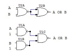
NAND and NOR gates have a remarkable characteristic, with enough of either one of them and connected in a certain way you can actually recreate the behavior of any other gate. This ability has made them very popular for large scale manufacturing of logic gates, since it is cheaper to build only one kind of device instead of having separate machines to create different logic gates for a single circuit.
Here are the circuit diagrams to create other gates with NAND and NOR.
AND gate:

OR gate:
NOT gate:

NAND gate:

NOR gate:

Since all digital electronic circuits are made with transistors, you can make all the above gates using them. When creating logic gates with transistors, the best option is to make them using NAND, NOR and simple NOT gates. The benefit of this is that any other gate can be constructed with a slight variation in the number and configuration of the transistors, instead of having several different circuits for each gate.
Logic gate's transistor diagrams:
NAND gate:

This gate is the simplest one to build with transistors, the NOT gate requires only one transistor. Here the transistor is configured so that when it is on (input 1), the circuit to ground is closed (output 0) and viceversa.
With these schematics and the above diagrams you can create a complete digital circuit using only transistors and resistors. Digital gates are very flexible, but up to a point. When creating a circuit that has more than three or four inputs, the circuit becomes too large to build using only logic gates, and that is where programmable devices come in handy, which we'll discuss in another article.
Digital electronics represent data (called bits) with only two states. Since in electronics we work with voltages, these two states are most times represented by a presence or lack of voltage. One (high state) in TTL logic familiy is represented by 5v, zero (low state) is represented by 0v (ground).
There are three basic gates: AND, OR, and NOT (Inverter).
Other common gates are NAND, NOR, XOR, XNOR (Equivalence). These gates are made with combinations of the basic logic gates. Its functions can be represented using a truth table, which lists every combination of inputs (A, B) and the resulting output (Z).
AND gate: two input gate, will output 1 when both inputs are 1. It is a one bit multiplication in Boolean algebra.
A B | Z
--------
0 0 | 0
0 1 | 0
1 0 | 0
1 1 | 1
--------
0 0 | 0
0 1 | 0
1 0 | 0
1 1 | 1
OR gate: two input gate, will output 1 when one or both inputs are 1. It is a one bit addition.
A B | Z
--------
0 0 | 0
0 1 | 1
1 0 | 1
1 1 | 1
--------
0 0 | 0
0 1 | 1
1 0 | 1
1 1 | 1
NOT gate or Inverter: one input gate, will output 1 when the input is 0 and viceversa.
A | Z
------
0 | 1
1 | 0
------
0 | 1
1 | 0
NAND gate: two input gate, same as AND gate but with a NOT at its output. Will output one as long as both its inputs are NOT 1. if none or one of the inputs is 0 it will output 1.
A B | Z
--------
0 0 | 1
0 1 | 1
1 0 | 1
1 1 | 0
--------
0 0 | 1
0 1 | 1
1 0 | 1
1 1 | 0
NOR gate: two input gate, same as OR gate but with a NOT at its output. Will output one as long as none of its inputs are 1. if both inputs are 0 it will output 1.
A B | Z
--------
0 0 | 1
0 1 | 0
1 0 | 0
1 1 | 0
--------
0 0 | 1
0 1 | 0
1 0 | 0
1 1 | 0
XOR gate: two input gate, will output 1 when one of its inputs is 1, but not both. This gate is actually a combination of gates, its boolean equation is A'B + AB'.
A B | Z
--------
0 0 | 0
0 1 | 1
1 0 | 1
1 1 | 0
--------
0 0 | 0
0 1 | 1
1 0 | 1
1 1 | 0
XNOR gate or Equivalence: two input gate, will output 1 when both its inputs are the same, either 0 or 1. XOR gate with a NOT at its output, its boolean equation is A'B' + AB.
A B | Z
--------
0 0 | 1
0 1 | 0
1 0 | 0
1 1 | 1
--------
0 0 | 1
0 1 | 0
1 0 | 0
1 1 | 1
Gate Diagrams:

Building other gates with NAND and NOR:
NAND and NOR gates have a remarkable characteristic, with enough of either one of them and connected in a certain way you can actually recreate the behavior of any other gate. This ability has made them very popular for large scale manufacturing of logic gates, since it is cheaper to build only one kind of device instead of having separate machines to create different logic gates for a single circuit.
Here are the circuit diagrams to create other gates with NAND and NOR.
AND gate:

OR gate:

NOT gate:

NAND gate:

NOR gate:

Since all digital electronic circuits are made with transistors, you can make all the above gates using them. When creating logic gates with transistors, the best option is to make them using NAND, NOR and simple NOT gates. The benefit of this is that any other gate can be constructed with a slight variation in the number and configuration of the transistors, instead of having several different circuits for each gate.
Logic gate's transistor diagrams:
NAND gate:

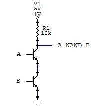
For this gate, the transistors are connected in series, so that the path from the output to ground is completed (thus giving 0 as output) only when both transistors are on (both inputs 1)
NOR gate:
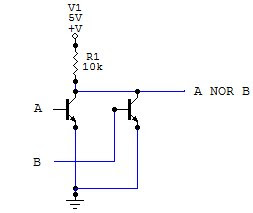
For the NOR gate, the transistors are connected in parallel, so that the circuit from the output to ground is closed when either transistor is on.
NOT gate:
This gate is the simplest one to build with transistors, the NOT gate requires only one transistor. Here the transistor is configured so that when it is on (input 1), the circuit to ground is closed (output 0) and viceversa.
Subscribe to:
Posts (Atom)