Digital electronics represent data (called bits) with only two states. Since in electronics we work with voltages, these two states are most times represented by a presence or lack of voltage. One (high state) in TTL logic familiy is represented by 5v, zero (low state) is represented by 0v (ground).
There are three basic gates: AND, OR, and NOT (Inverter).
Other common gates are NAND, NOR, XOR, XNOR (Equivalence). These gates are made with combinations of the basic logic gates. Its functions can be represented using a truth table, which lists every combination of inputs (A, B) and the resulting output (Z).
AND gate: two input gate, will output 1 when both inputs are 1. It is a one bit multiplication in Boolean algebra.
A B | Z
--------
0 0 | 0
0 1 | 0
1 0 | 0
1 1 | 1
--------
0 0 | 0
0 1 | 0
1 0 | 0
1 1 | 1
OR gate: two input gate, will output 1 when one or both inputs are 1. It is a one bit addition.
A B | Z
--------
0 0 | 0
0 1 | 1
1 0 | 1
1 1 | 1
--------
0 0 | 0
0 1 | 1
1 0 | 1
1 1 | 1
NOT gate or Inverter: one input gate, will output 1 when the input is 0 and viceversa.
A | Z
------
0 | 1
1 | 0
------
0 | 1
1 | 0
NAND gate: two input gate, same as AND gate but with a NOT at its output. Will output one as long as both its inputs are NOT 1. if none or one of the inputs is 0 it will output 1.
A B | Z
--------
0 0 | 1
0 1 | 1
1 0 | 1
1 1 | 0
--------
0 0 | 1
0 1 | 1
1 0 | 1
1 1 | 0
NOR gate: two input gate, same as OR gate but with a NOT at its output. Will output one as long as none of its inputs are 1. if both inputs are 0 it will output 1.
A B | Z
--------
0 0 | 1
0 1 | 0
1 0 | 0
1 1 | 0
--------
0 0 | 1
0 1 | 0
1 0 | 0
1 1 | 0
XOR gate: two input gate, will output 1 when one of its inputs is 1, but not both. This gate is actually a combination of gates, its boolean equation is A'B + AB'.
A B | Z
--------
0 0 | 0
0 1 | 1
1 0 | 1
1 1 | 0
--------
0 0 | 0
0 1 | 1
1 0 | 1
1 1 | 0
XNOR gate or Equivalence: two input gate, will output 1 when both its inputs are the same, either 0 or 1. XOR gate with a NOT at its output, its boolean equation is A'B' + AB.
A B | Z
--------
0 0 | 1
0 1 | 0
1 0 | 0
1 1 | 1
--------
0 0 | 1
0 1 | 0
1 0 | 0
1 1 | 1
Gate Diagrams:

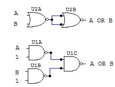
Building other gates with NAND and NOR:
NAND and NOR gates have a remarkable characteristic, with enough of either one of them and connected in a certain way you can actually recreate the behavior of any other gate. This ability has made them very popular for large scale manufacturing of logic gates, since it is cheaper to build only one kind of device instead of having separate machines to create different logic gates for a single circuit.
Here are the circuit diagrams to create other gates with NAND and NOR.
AND gate:

OR gate:

NOT gate:

NAND gate:

NOR gate:

Since all digital electronic circuits are made with transistors, you can make all the above gates using them. When creating logic gates with transistors, the best option is to make them using NAND, NOR and simple NOT gates. The benefit of this is that any other gate can be constructed with a slight variation in the number and configuration of the transistors, instead of having several different circuits for each gate.
Logic gate's transistor diagrams:
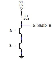
NAND gate:

For this gate, the transistors are connected in series, so that the path from the output to ground is completed (thus giving 0 as output) only when both transistors are on (both inputs 1)
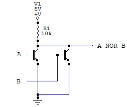
NOR gate:
For the NOR gate, the transistors are connected in parallel, so that the circuit from the output to ground is closed when either transistor is on.
NOT gate:With these schematics and the above diagrams you can create a complete digital circuit using only transistors and resistors. Digital gates are very flexible, but up to a point. When creating a circuit that has more than three or four inputs, the circuit becomes too large to build using only logic gates, and that is where programmable devices come in handy, which we'll discuss in another article.
