.
You can find many more electronic circuits for beginners by clicking the link!

Amplifiers

Amplifiers increase either the amplitude (voltage) or power (Amperage/Current)
applied to its input.

Components of an amplifier:

Gain component: The main component of the amplifier, defines many of its characteristics like noise, bandwidth, gain, input and output impedance, and others.

Bias: Some types of components need a bias point in order to operate correctly. The bias point is a dc voltage applied to the input of the amplifier. There are many ways to set the bias point,
depending on the gain component used.

Accessories: These are many kinds of sub-circuits used to fine tune the operation of the amplifier, including preamplifiers, buffers, stabilizers, filters, limiters, etc..

Stages of Amplifiers:

Input: This stage consists of a signal from another subsystem outside the amplifier, or a sensor like a microphone, photodiode or any other component that delivers a small signal. Depending on
the intended purpose and input signal, this stage may contain a preamplifier, which is a signal (voltage) amplification before the main power (current) amplification stage, and a filter to
limit incoming frequencies.

Amplification: Main stage of any amplifier, most of the times it is a power amplification process, sometimes with signal amplification as well. This stage is where the gain component and many of the accessories like stabilizers and limiters are located.

Output: Last stage, sometimes consists of a buffer and/or filter to remove any noise generated in the main amplification stage. The buffer sometimes added to deliver more current (lower output impedance).


Block Diagram of a Amplifiers
(Click to enlarge)


Description of Amplifier accessories:

Coupling: This is usually done with a capacitor. The purpose of the coupling capacitor is to prevent any DC voltage from modifying the bias point of the amplifier, to prevent clipping (driving the signal to the max voltage, distorting it) from a high or low bias point.

Another coupling method is using transformers. This is done on lower frequency signals where the reactance (resistance-like behavior when a component is applied an AC voltage) of capacitors is so high to the point the signal is practically lost.

A third choice is using tuned transformers, by using a capacitor in parallel with the transformer. This creates a tuned circuit that has a very narrow bandwidth, useful in some special interest amplifiers.

Filters: This topic is so extensive it deserves its own article. Amplifiers have uses for filters to limit noise and reject unwanted signals from its input. Combining a filter and an amplifier creates an active filter (filter that has gain).

Most filters use RC networks to create the filter, although RL or RLC are also used in some designs.

Stabilizers: This is usually some kind of feedback used to prevent clipping or other circuitry to keep the frequency within a certain range (stop frequency drifting).

Limiters: Sometimes only voltages up to a certain point are needed or desired, here limiters come into use. They limit or sometimes clip a signal if it goes above a certain voltage, other kind of limiters use feedback to control the gain of the amplifier so as to keep the output signal within the specified voltage range.

Buffers: Also called voltage followers, this is just another name for another stage of amplification with a gain of 1. This is to provide more current and avoid overloading the main amplifier, as doing so can reduce either the gain or bandwidth.

If you need a specific implementation of an amplifier circuit, you may want to consider learning all the abstract theory first and then moving on to the components page, where all component-specific circuits and modes of operation are listed.

Types of circuits

From the smallest circuit to the largest electronics project, every circuit that performs a useful function has one or more of the same building blocks. I’m not talking about electronic components; I’m talking about sub-circuits that have a defined function.

These circuits are divided in digital and analog. In these pages you’ll learn how to design every type of circuit listed, with emphasis on a functionality level, instead of a component level, in order to be able to create any kind of amplifier as required by the project. Here’s the list of them:

Analog
  • Amplifiers
  • Filters
  • Power sources
  • Oscillators
  • Rectifiers
  • Timers
  • Modulators
  • Demodulators
Digital
  • Logic gates
  • Counters
  • Encoders
  • Decoders
  • Flip-Flops
  • Multiplexers
  • Demultiplexers
  • Analog to Digital Converter (ADC)
  • Digital to Analog Converter (DAC)
  • Microcontrollers
  • Microprocessors
All of these sub-circuits have a defined function within a complete project, and some of them are even a project on their own. These categories are somewhat broad; every one of them has many different designs and implementations depending on the particular characteristics of the project, for example amplifiers.

There are transistor and OpAmp amplifiers. In transistor amplifiers there are common source, common base, common collector, there are Darlington amplifiers. Transistor amplifiers are further divided by the kind of transistor used: BJT, N-channel JFET, P-channel JFET, MosFET, Nmos, Pmos, Cmos; Each with its own set of configurations.

On OpAmp there are negative feedback, positive feedback, voltage follower and others.
As you can see there are a million different combinations of amplifier topologies as they are called, way too many to be familiar with all of them.

Audio Amplifier

Here is a simple audio amplifier circuit that is easy to build and has few components. This circuit is built around the LM386 (click for datasheet) audio amplifier integrated circuit, useful when you need to power medium sized speakers from a music player that can only drive earphones.

How it works:

From left to right, the first part is the input stage, here is the connector to the audio source connected too the circuit using a capacitor. This capacitor passes only the audio, and blocks any direct current that may affect the function of the amplifier. Next to the capacitor is a variable transistor (potenciometer), this is used as a volume control.

Next is the LM386 itself, this amplifies the audio input using energy from the battery it is connected to. You'll notice there are two capacitors connected to it, one above and one below in the schematic. The top one is connected from pin 1 (positive side of capacitor) to pin 8 (negative side), this is to get the maximum amplification this IC can generate. The bottom one is also there to help get maximum amplification, this one goes connected from pin 7 (positive) to ground.

Last is the output stage, it is made with two capacitors, one resistor and the speaker. The resistor and capacitor that are connected before the speaker form a filter, that attenuates high frequency signals coming from the amplifier, most likely noise picked up or generated in the amplifying process. The capacitor connected to the speaker is there for the same reason we used a capacitor in the input stage, to prevent direct current from causing undesired operation of the speaker.

amplifier circuit using 386 electronic circuit
(click to enlarge)

Led Flasher Circuit

This circuit is built around one of the most popular timer integrated circuits, the 555 timer.

This circuit will flash the led on and of at regular intervals.

How it works:

From left to right, the two resistors and the capacitor set the time it takes to turn the led on or off, by changing the time it takes to charge the capacitor to trigger the timer. Next is the 555 timer, this is where all the work gets done to determine the time the led stays on and off. It contains a complicated circuit inside, but since it is packaged in the IC it can be used as a simple component.

The two capacitors that are right of the timer are just accessories so to speak, but are needed for the timer to work correctly. The last part is the resistor and the led, the resistor is there to limit the current on the led so that it won't burn.

555 led flasher circuit
(click to enlarge)

(click to enlarge)
(pin numbers on actual IC)

Simple FM Transmitter

This circuit uses a small microphone to capture the sound and some transistors to generate radio waves that can be picked up by a FM receiver like a car stereo.

How it works:

From left to right, the first part is the microphone and some resistors to get it working. Next we have a capacitor and the first transistor, this amplifies the sound from the microphone so that it can be loud enough to work with. The last part, there is a transistor, a coil and some capacitors. This part generates the radio waves and combines them with the sound from the mic to transmit it thru the antenna.

The coil is made with about 9 turns of wire, use a pencil to get the right diameter for the coil. The capacitor with the arrow is called a trimmer capacitor, it has a small screw to adjust the value, we'll use it to tune a certain frequency or station to transmit on.

simple fm radio transmitter(click to enlarge)

Logic Gates

Logic gates are the basic building blocks of digital electronics. These are circuits made out of transistors that perform a a logical operation (see Boolean algebra).

Digital electronics represent data (called bits) with only two states. Since in electronics we work with voltages, these two states are most times represented by a presence or lack of voltage. One (high state) in TTL logic familiy is represented by 5v, zero (low state) is represented by 0v (ground).

There are three basic gates: AND, OR, and NOT (Inverter).
Other common gates are NAND, NOR, XOR, XNOR (Equivalence). These gates are made with combinations of the basic logic gates. Its functions can be represented using a truth table, which lists every combination of inputs (A, B) and the resulting output (Z).

AND gate: two input gate, will output 1 when both inputs are 1. It is a one bit multiplication in Boolean algebra.

A B | Z
--------
0 0 | 0
0 1 | 0
1 0 | 0
1 1 | 1

OR gate: two input gate, will output 1 when one or both inputs are 1. It is a one bit addition.

A B | Z
--------
0 0 | 0
0 1 | 1
1 0 | 1
1 1 | 1


NOT gate or Inverter: one input gate, will output 1 when the input is 0 and viceversa.

A | Z
------
0 | 1
1 | 0


NAND gate: two input gate, same as AND gate but with a NOT at its output. Will output one as long as both its inputs are NOT 1. if none or one of the inputs is 0 it will output 1.

A B | Z
--------
0 0 | 1
0 1 | 1
1 0 | 1
1 1 | 0


NOR gate: two input gate, same as OR gate but with a NOT at its output. Will output one as long as none of its inputs are 1. if both inputs are 0 it will output 1.

A B | Z
--------
0 0 | 1
0 1 | 0
1 0 | 0
1 1 | 0

XOR gate: two input gate, will output 1 when one of its inputs is 1, but not both. This gate is actually a combination of gates, its boolean equation is A'B + AB'.

A B | Z
--------
0 0 | 0
0 1 | 1
1 0 | 1
1 1 | 0

XNOR gate or Equivalence: two input gate, will output 1 when both its inputs are the same, either 0 or 1. XOR gate with a NOT at its output, its boolean equation is A'B' + AB.

A B | Z
--------
0 0 | 1
0 1 | 0
1 0 | 0
1 1 | 1

Gate Diagrams:
Basic logic gates diagrams

Building other gates with NAND and NOR:

NAND and NOR gates have a remarkable characteristic, with enough of either one of them and connected in a certain way you can actually recreate the behavior of any other gate. This ability has made them very popular for large scale manufacturing of logic gates, since it is cheaper to build only one kind of device instead of having separate machines to create different logic gates for a single circuit.

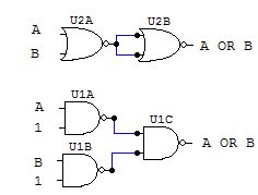
Here are the circuit diagrams to create other gates with NAND and NOR.

AND gate:
AND equivalent with NAND and NOR gates
OR gate:
OR gate with NAND and NOR diagram
NOT gate:
NOT gate with NAND and NOR diagram
NAND gate:
NAND gate with NAND and NOR diagram
NOR gate:
NOR gate with NAND and NOR diagram
Since all digital electronic circuits are made with transistors, you can make all the above gates using them. When creating logic gates with transistors, the best option is to make them using NAND, NOR and simple NOT gates. The benefit of this is that any other gate can be constructed with a slight variation in the number and configuration of the transistors, instead of having several different circuits for each gate.

Logic gate's transistor diagrams:

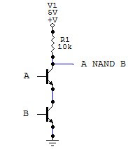
NAND gate:
NAND logic gate made with transistors
For this gate, the transistors are connected in series, so that the path from the output to ground is completed (thus giving 0 as output) only when both transistors are on (both inputs 1)

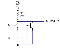
NOR gate:
NOR logic gate made with transistors
For the NOR gate, the transistors are connected in parallel, so that the circuit from the output to ground is closed when either transistor is on.

NOT gate:
NOT logic gate made with transistors
This gate is the simplest one to build with transistors, the NOT gate requires only one transistor. Here the transistor is configured so that when it is on (input 1), the circuit to ground is closed (output 0) and viceversa.

With these schematics and the above diagrams you can create a complete digital circuit using only transistors and resistors. Digital gates are very flexible, but up to a point. When creating a circuit that has more than three or four inputs, the circuit becomes too large to build using only logic gates, and that is where programmable devices come in handy, which we'll discuss in another article.

Welcome To Electronic Circuits For Beginners!

All circuits included here are recommended to be assembled in printed circuit boards. Printed circuit boards, or PCB's increase the circuit reliability and mechanical stability.

Circuits quick links:

-

Simple FM Transmitter

-

Led Flasher Circuit

-

Quadrocopters for beginners

-

Voltage follower circuit

-

Beginners Audio Amplifier

-

Led chaser circuit

-

Tone generator circuit

-

H bridge circuit

-

Simple power supply

-

Beginner Electronics mini course index

-

All circuits include parts list and complete How-it-works for beginners and hobbyists to easily understand.